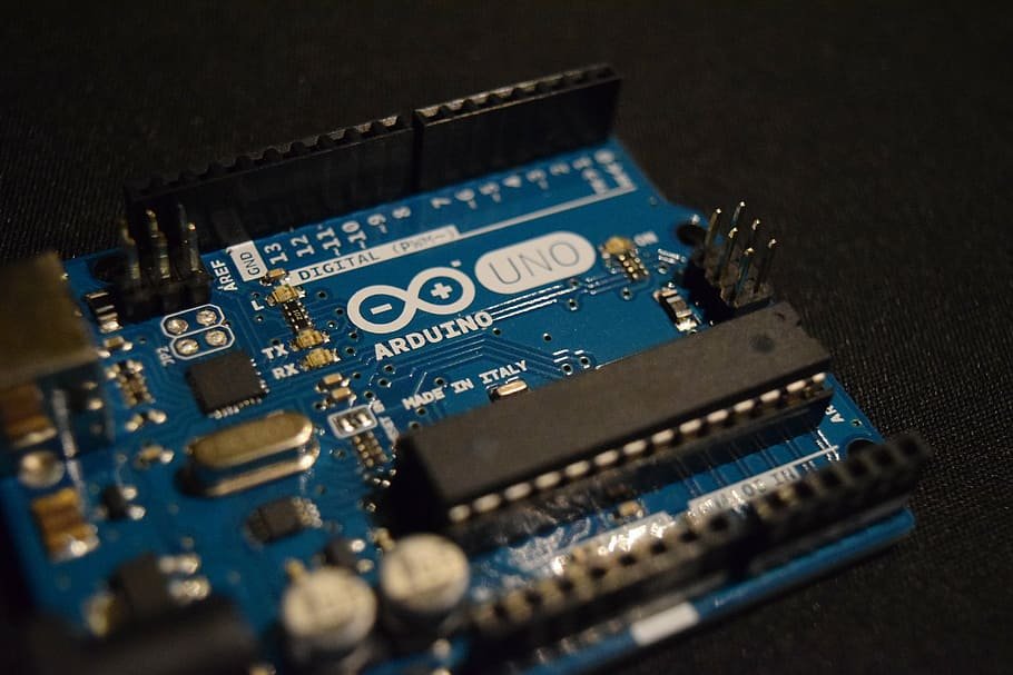
The Arduino UNO R3 is a frequently used microcontroller board in the family of an Arduino. This is the latest third version of an Arduino board and released in the year 2011. The main advantage of this board is if we make a mistake we can change the microcontroller on the board. The main features of this board mainly include, it is available in DIP (dual-inline-package), detachable and ATmega328 microcontroller. The programming of this board can easily be loaded by using an Arduino computer program. This board has huge support from the Arduino community, which will make a very simple way to start working in embedded electronics, and many more applications.
What is Arduino Uno R3?
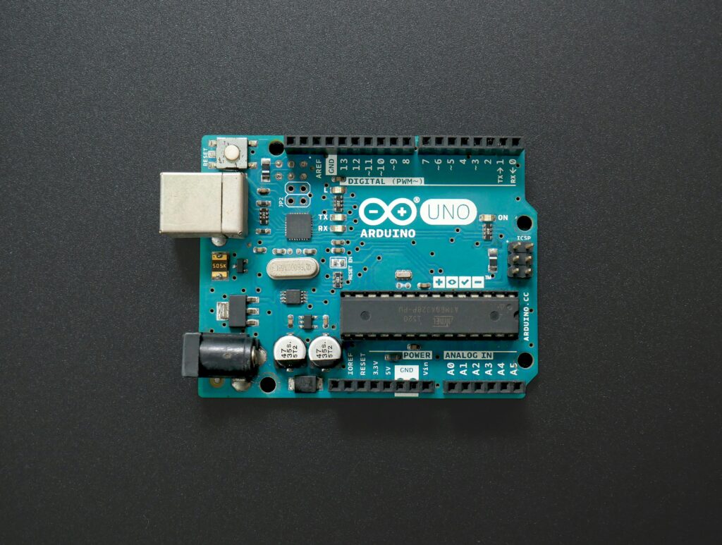
The Arduino Uno is an open-source microcontroller board based on the Microchip ATmega328P microcontroller (MCU). It includes the whole thing required to hold up the microcontroller; just attach it to a PC with the help of a USB cable, and give the supply using AC-DC adapter or a battery to get started. The term Uno means “one” in the language of “Italian” and was selected for marking the release of Arduino’s IDE 1.0 software. The R3 Arduino Uno is the 3rd as well as most recent modification of the Arduino Uno. Arduino board and IDE software are the reference versions of Arduino and are currently progressed to new releases. The Uno-board is the primary in a sequence of USB-Arduino boards, & the reference model designed for the Arduino platform.
Arduino Uno R3 Specifications
The Arduino Uno R3 board includes the following specifications.
- It is an ATmega328P based Microcontroller
- The Operating Voltage of the Arduino is 5V
- The recommended input voltage ranges from 7V to 12V
- The i/p voltage (limit) is 6V to 20V
- Digital input and output pins 14
- Digital input & output pins (PWM)-6
- Analog i/p pins are 6
- DC Current for each I/O Pin is 20 mA
- DC Current used for 3.3V Pin is 50 mA
- Flash Memory -32 KB, and 0.5 KB memory is used by the boot loader
- SRAM is 2 KB
- EEPROM is 1 KB
- The speed of the CLK is 16 MHz
- In Built LED
- The length and width of the Arduino are 68.6 mm X 53.4 mm
- The weight of the Arduino board is 25 g
Arduino Uno R3 Pin Diagram
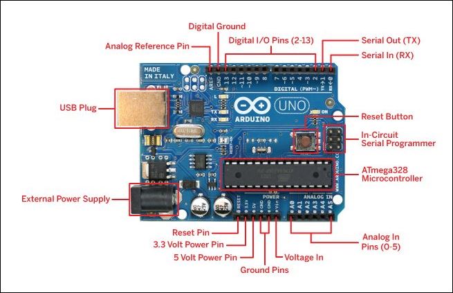
The Arduino Uno R3 pin diagram is shown below. It comprises 14-digit I/O pins. From these pins, 6-pins can be utilized like PWM outputs. This board includes 14 digital input/output pins, Analog inputs-6, a USB connection, quartz crystal-16 MHz, a power jack, a USB connection, resonator-16Mhz, a power jack, an ICSP header an RST button.
Power Supply
The power supply of the Arduino can be done with the help of an exterior power supply otherwise USB connection. The exterior power supply (6 to 20 volts) mainly includes a battery or an AC to DC adapter. The connection of an adapter can be done by plugging a center-positive plug (2.1mm) into the power jack on the board. The battery terminals can be placed in the pins of Vin as well as GND. The power pins of an Arduino board include the following.
Vin: The input voltage or Vin to the Arduino while it is using an exterior power supply opposite to volts from the connection of USB or else RPS (regulated power supply). By using this pin, one can supply the voltage.
5Volts: The RPS can be used to give the power supply to the microcontroller as well as components that are used on the Arduino board. This can be approached from the input voltage through a regulator.
3V3: A 3.3 supply voltage can be generated with the onboard regulator, and the highest draw current will be 50 mA.
GND: GND (ground) pins
Memory
The memory of an ATmega328 microcontroller includes 32 KB and 0.5 KB memory is utilized for the Boot loader), and also it includes SRAM-2 KB as well as EEPROM-1KB.
Input and Output
We know that an arguing Uno R3 includes 14-digital pins which can be used as an input otherwise output by using functions like pin Mode (), digital Read(), and digital Write(). These pins can operate with 5V, and every digital pin can give or receive 20mA, & includes a 20k to 50k ohm pull-up resistor. The maximum current on any pin is 40mA which cannot surpass for avoiding the microcontroller from damage. Additionally, some of the pins of an Arduino include specific functions.
Serial Pins
The serial pins of an Arduino board are TX (1) and RX (0) pins and these pins can be used to transfer the TTL serial data. The connection of these pins can be done with the equivalent pins of the ATmega8 U2 USB to TTL chip.
External Interrupt Pins
The external interrupt pins of the board are 2 & 3, and these pins can be arranged to activate an interrupt on a rising otherwise falling edge, a low-value otherwise a modified value
PWM Pins
The PWM pins of an Arduino are 3, 5, 6, 9, 10, & 11, and gives an output of an 8-bit PWM with the function analog Write ().
SPI (Serial Peripheral Interface) Pins
The SPI pins are 10, 11, 12, 13 namely SS, MOSI, MISO, SCK, and these will maintain the SPI communication with the help of the SPI library.
LED Pin
An arguing board is in built with an LED using digital pin-13. Whenever the digital pin is high, the LED will glow otherwise it will not glow.
TWI (2-Wire Interface) Pins
The TWI pins are SDA or A4, & SCL or A5, which can support the communication of TWI with the help of the Wire library.
AREF (Analog Reference) Pin
An analog reference pin is the reference voltage to the inputs of an analog i/ps using a function like analog Reference().
Reset (RST) Pin
This pin brings a low line for resetting the microcontroller, and it is very useful for using an RST button toward shields which can block the one over the Arduino R3 board.
Communication
The communication protocols of an Arduino Uno include SPI, I2C, and UART serial communication.
UART
An Arduino Uno uses the two functions like the transmitter digital pin1 and the receiver digital pin0. These pins are mainly used in UART TTL serial communication.
I2C
An Arduino UNO board employs SDA pin otherwise A4 pin & A5 pin otherwise SCL pin is used for I2C communication with wire library. In this, both the SCL and SDA are CLK signal and data signal.
SPI Pins
The SPI communication includes MOSI, MISO, and SCK.
MOSI (Pin11)
This is the master out slave in the pin, used to transmit the data to the devices
MISO (Pin12)
This pin is a serial CLK, and the CLK pulse will synchronize the transmission of which is produced by the master.
SCK (Pin13)
The CLK pulse synchronizes data transmission that is generated by the master. Equivalent pins with the SPI library is employed for the communication of SPI. ICSP (in-circuit serial programming) headers can be utilized for programming the ATmega microcontroller directly with the boot loader.
Arduino Uno R3 Programming
- The programming of an Arduino Uno R3 can be done using IDE software. The microcontroller on the board will come with pre-burned by a boot loader that permits to upload of fresh code without using an exterior hardware programmer.
- The communication of this can be done using a protocol like STK500.
- We can also upload the program in the microcontroller by avoiding the boot loader using the header like the In-Circuit Serial Programming.
Arduino Uno R3 Projects
The applications of Arduino Uno mainly involves in Arduino Uno based projects which include the following
- Visitor Alarm in Office using Arduino Uno
- Arduino Uno based Soccer Robot
- Arduino Uno based Automatic Medication Reminder
- Motion Detecting with Static Electricity
- Arduino Uno based Taxi with Digital Fare Meter
- Arduino Uno based Smart Stick
- Robot Car Controlled by Smartphone and Arduino