In power electronics, pulse width modulation is a proven effective technique that is used to control semiconductor devices. Pulse width modulation or PWM is a commonly used control technique that generates analog signals from digital devices such as microcontrollers. The signal thus produced will have a train of pulses, and these pulses will be in the form of square waves. Thus, at any given time, the wave will either be high or low. Let us learn more about pulse width modulation in this article.
What is Pulse Width Modulation?
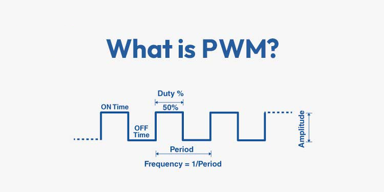
Pulse-width modulation is a digital technique to control a signal by repeatedly toggling a signal between a HIGH and a LOW state in a consistent pattern. We can portray new information by changing how long the signal is HIGH versus LOW. The PWM signal has two key parameters—frequency and duty cycle.
Pulse-Width-Modulation explained
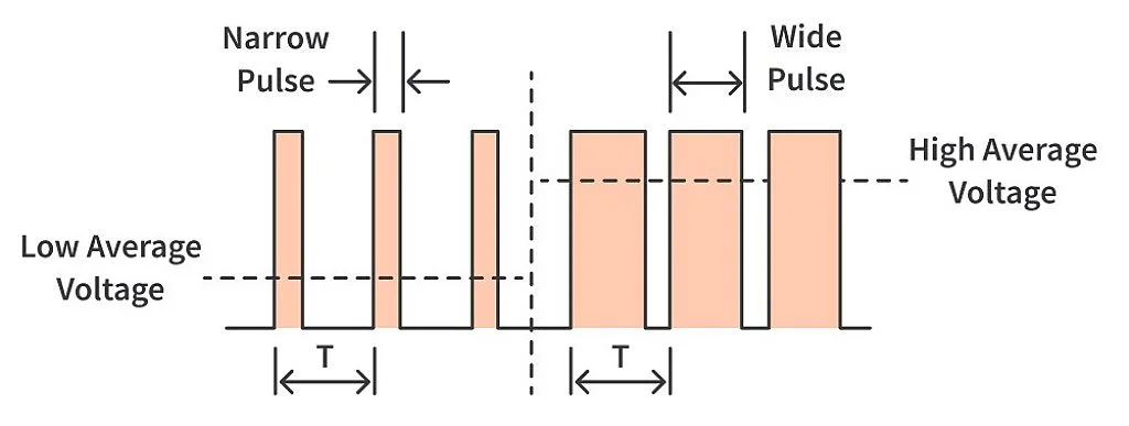
With electrical components, you can control the current delivered to them, even if the only control you have is switching the power supply on and off. You can rapidly switch the power supply on and off in a pattern to control the current delivered to the device. Keeping it “on” for a duration more than the “off” duration will raise the average power level and doing it the opposite way will reduce the average power level. We can generate a varied range of speeds (analog) for our motors and actuators even though in reality we are just switching between the two possible states of being on and off (digital). This is exactly what a PWM signal is.
Let’s use this analogy as an example. Imagine you have a ceiling fan in your home but without any speed regulator. So you can either turn it on and it’ll gradually achieve max speed, or you can turn it off. Now, what if I ask you to run the fan at 50% of its max speed. Is it possible without a speed regulator? Give this question a thought. The answer is yes, it is possible. While we don’t recommend actually doing this, you can achieve it by playing a little with the switch of the ceiling fan. We know that the fan will not instantly achieve the max speed the moment we turn it on and neither will it immediately come to a halt as we turn it off. Turn on the switch, wait until you see that the fan has achieved 50% of the speed, and turn off the switch. Switch it on again as it starts to slow down. Using this delay to our advantage, we can switch it on or off, making it faster or slower, to get the speed we want. An important thing to note here is that continuous switching of the fan will make it draw a large amount of current, so again, we discourage you from doing this in real life.
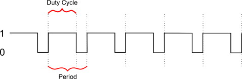
The switching on and off is the pulse. The duration for which the pulse is held at a high state is the pulse width. T represents the total time taken to complete a cycle. Modulation refers to the modification of the original signal to get our desired signal. So we are modifying a signal or pulse such that it is “on” for the duration as per our need, hence, Pulse-Width-Modulation.
Duty Cycle
In signals, we define logic high as “on-time”. To represent the duration of “on-time”, we use the concept of duty cycle. In simple terms, the duty cycle describes the percentage of time a digital signal is “on” over an interval or period. It is represented in percentage (%).
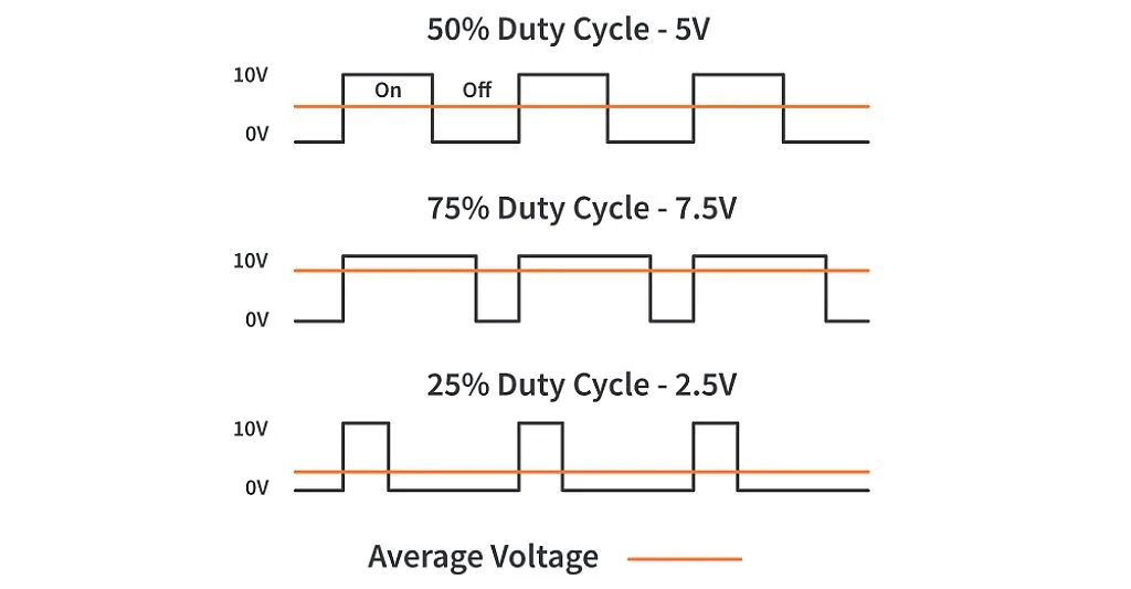
Let’s take a signal with a maximum voltage of 10V. If our signal takes one second to complete a cycle and the signal is on for 0.5 seconds and off for the other 0.5 seconds, this is called a 50% duty cycle and we will get 5V as the average voltage output. If the signal is on for 0.75 seconds and off for the other 0.25 seconds, it will be a 75% duty cycle and the output will be 7.5V. The below image represents signals having different duty cycles and the average voltage generated by them:
Duty cycles make PWM what they actually are. We get different PWM signals by varying duty cycles of the signal. The duty cycle can be calculated as per the below formula:
![]()
where
D = Duty Cycle in Percentage
Ton = Duration of the signal being in the “on” state
Period = Total time taken to complete one cycle (Ton + Toff)
After we’ve calculated the duty cycle, we can calculate the average voltage of the signal using the following formula:
![]()
where
Vavg = Average voltage of the signal
D = Duty Cycle in Percentage
Vmax = Max voltage of the signal
Frequency
Just like the duty cycle, frequency is also a primary component that defines a PWM signal’s behavior. It is the number of times a signal repeats per second. The frequency required depends on the application. For example, the frequency of a PWM signal should be sufficiently high if we wish to see a proper dimming effect while controlling LEDs. A duty cycle of 20% at 1 Hz will be noticeable to the human eye that the LED is turning ON and OFF. However, if we increase the frequency to 100Hz, we’ll get to see the proper dimming of the LED.
Generation of PWM in microcontrollers
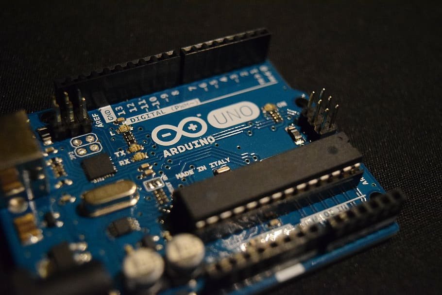
There are various ways to generate a PWM signal. We can use a 555 Timer IC or even a comparator circuit to generate one. But the easiest way to see a PWM in action is by using a microcontroller. We can generate a PWM signal with popular microcontroller boards like the Arduino Uno just by typing out a couple of lines in our code! The PWM circuitry present on microcontrollers uses timers in the backend but they are internally connected with the pins to make our job easier. For example, if we wish to generate a PWM signal to vary the speed of a DC motor with our Arduino Uno, we can use the analogWrite(pin, value) function of Arduino. However, the crucial thing to note here is that not all the pins of an Arduino Uno are capable of generating a PWM signal. In the case of Arduino Uno, there are only 6 I/O pins (3,5,6,9,10,11) that support PWM generation and they are marked with a tilde (~) in front of their pin number on the board.
The analogWrite() function supports values from 0 to 255, where passing 0 represents 0% duty cycle and 255 represents a 100% duty cycle.
analogWrite(PWM_PIN, 64); // 25% Duty Cycle or 25% of max speed analogWrite(PWM_PIN, 127); // 50% Duty Cycle or 50% of max speed analogWrite(PWM_PIN, 191); // 75% Duty Cycle or 75% of max speed analogWrite(PWM_PIN, 255); // 100% Duty Cycle or full speed
Other microcontrollers can be more complicated in their implementation but at the lowest level, they are usually operating on the same principles.
Applications
We can control the power delivered to electrical devices using Pulse Width Modulation (PWM) signals. Now, because of its high efficiency, low power loss, and its ability to precisely control the power, this technique is used in many applications like:
Controlling the speed of DC motors and servo motors.
Dimming of LEDs and soft-blinking. Lights can go from full intensity to dark slowly and slowly raised to full intensity again using PWM.
Encoding data and transmitting over a data line in telecommunications.
Creating different audio effects.